
Selecting a CNC vertical machining center (VMC) is not about picking the model with the highest specifications — it is about matching machine capabilities to your actual production requirements. The right choice depends on five factors: workpiece size and travel requirements, material type and spindle characteristics, accuracy and repeatability needs, tool magazine and automation level, and configuration flexibility. This guide walks through each step to help you make an informed decision.
The most fundamental selection criterion is whether the machine's axis travels can accommodate your largest workpiece — and leave room for fixtures and tool access.
X-axis travel determines the maximum workpiece length that can be machined in one setup. Y-axis travel defines the width capacity, while Z-axis travel controls the vertical clearance available between the spindle and the worktable.
For small to medium mold components and automotive parts, a machine with X-axis travel of 800–1000 mm and Y-axis travel of 550 mm may be sufficient. For larger dies, aerospace structural parts, or engineering machinery components, travels of 1300 mm or more in X and 700 mm or more in Y are typically required.
It is also important to check the distance from spindle nose to worktable — this determines the maximum workpiece height you can accommodate, as well as the clearance needed for longer tools.
| Workpiece Size Range | Recommended X-Axis Travel | Recommended Y-Axis Travel | Typical Machine Series |
|---|---|---|---|
| Small molds, fixtures | 800–1000 mm | 550 mm | EV-855A / EV-1055A |
| Medium dies, automotive parts | 1100–1400 mm | 650–720 mm | EV-1165A / EV-1370A |
| Large molds, aerospace structures | 1400–1800 mm | 750–900 mm | EV-1475B / EV-1580B / EV-1890B |
Beyond physical dimensions, consider the worktable load capacity. Heavier workpieces require stronger tables and more robust guideways. Capacities typically range from 650 kg on smaller machines to 1800 kg on larger models.
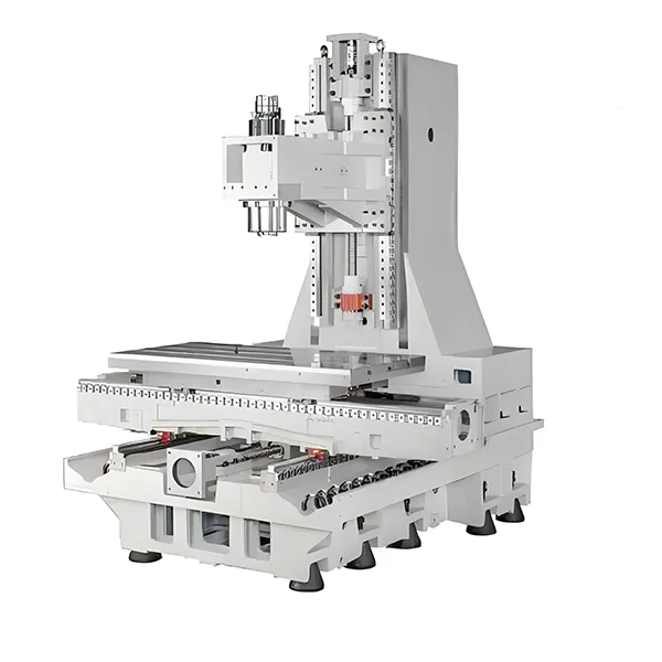
For detailed travel specifications across different models, explore the available cnc machining centers configurations.
Different materials demand different spindle characteristics. The two key variables are spindle speed and spindle torque — and they often trade off against each other.
High-speed spindles (10,000–15,000 rpm) are suitable for:
High-torque spindles (with larger motor power) are suitable for:
A machine's main motor power and torque output directly affect its cutting capability. For example, smaller EV-series models with ISO 40 taper typically offer 11/18.5 kW power and 52.5/118 Nm torque, while larger ISO 50 taper models deliver 22/33 kW and 140/260 Nm torque — with optional high-torque configurations reaching 210/380 Nm.
| Material Type | Recommended Spindle Speed | Recommended Spindle Taper | Typical Application |
|---|---|---|---|
| Aluminum, light alloys | 10,000–15,000 rpm | ISO 40 / BT40 | High-speed machining, finishing |
| Steel, cast iron | 8,000–10,000 rpm | ISO 40 / BT40 | General-purpose machining |
| Hardened steel, tough alloys | 6,000–8,000 rpm | ISO 50 / BT50 | Heavy cutting, roughing |
The spindle taper also matters: ISO 40 / BT40 is common for general-purpose machining, while ISO 50 / BT50 provides greater rigidity for heavy cuts and larger tools. Some machines offer multiple spindle drive options — belt-driven, direct-drive, or electric spindle — allowing further customization based on specific speed and torque requirements.
Positioning accuracy and repeatability are critical for high-precision applications such as mold making, aerospace components, and automotive powertrain parts.
Positioning accuracy refers to how closely the machine can position the tool to a commanded point. Repeat positioning accuracy indicates how consistently the machine returns to the same position across multiple cycles.
For most precision machining applications, positioning accuracy of 0.008 mm and repeatability of 0.005 mm are considered high-performance benchmarks. Larger machines may have slightly lower specifications — 0.009 mm positioning and 0.006 mm repeatability — which is still suitable for most heavy-duty applications.
Several design features contribute to long-term accuracy stability:
For applications demanding the highest precision — such as finishing molds with tight tolerances — optional Heidenhain scales on all axes can provide additional position feedback and compensation.
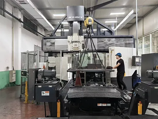
The tool magazine is often overlooked in initial selection, yet it directly impacts machining efficiency and the complexity of parts you can produce.
Tool magazine capacity determines how many different tools can be loaded simultaneously. A 24-tool capacity is standard for most general-purpose VMCs. This is sufficient for:
For more complex parts requiring multiple operations — such as aerospace components with many drilled holes, tapped features, and contoured surfaces — larger capacity may be beneficial. Optional 32-position magazines are available for applications requiring more tool variety.
Other tool-related considerations include:
If your production involves unattended machining or high-volume runs, consider automation features such as automatic chip conveyors (chain-type, scraper, or spiral), pallet changers, or robotic loading systems.
The final step is not about the machine itself — it is about how the machine can adapt to evolving production requirements.
A machine that offers configuration options at the time of purchase — and upgrade paths afterward — provides long-term value beyond the initial investment.
Key configuration considerations include:
Spindle options:
4th and 5th axis capability:
Measurement and compensation:
Coolant and chip management:
To ensure your selection aligns with your production goals, compare them against your checklist and review the available options for each model.
Use this checklist to organize your requirements before contacting a supplier:
Positioning accuracy is how close the machine can get to a commanded position on the first attempt. Repeatability is how consistently it returns to that same position over multiple attempts — a more critical metric for production consistency.
ISO 40 is suitable for general-purpose machining with tool weights up to 8 kg and diameters up to 150 mm. ISO 50 provides greater rigidity for heavy cutting, larger tools, and tougher materials like hardened steel.
Yes, with an optional 4-axis rotary table, a 3-axis VMC can perform 5-face machining in a single setup, reducing fixturing time and improving accuracy.
Key factors include the quality of castings, annealing and stress-relief processes, guideway and ballscrew quality, thermal management, and regular maintenance.
Machine footprints vary significantly. Smaller models like the EV-855A measure approximately 2700×2400 mm, while larger models like the EV-1890B require approximately 4300×3400 mm. Always account for additional space for chip conveyors, coolant tanks, and operator access.
Choosing a CNC vertical machining center is a decision that should be driven by your specific production requirements — not by specifications alone. The five steps outlined above — matching travel to workpiece size, selecting spindle characteristics for your materials, defining accuracy needs, evaluating tool magazine capacity, and planning for configuration flexibility — provide a framework for making a confident, well-informed choice.
The most common mistake buyers make is selecting a machine that is either under-specified for their current needs or over-specified for their actual requirements. Start with your workpiece, work backward to the machine specifications, and always leave room for future growth.
Once you have defined your requirements, the next step is to review the available configurations and compare them against your checklist. For detailed specifications of EV-series vertical machining centers — including travel ranges, spindle options, and available configurations — explore the EV Series 3/4 Axis VMC product page. For application-specific questions, consult with a technical engineer to confirm the specification that best fits your production setup.


 English
 中文
中文 Pусский

