The EUMASEIKI DM/DM5 series gantry machining center, with its high torque power, high rigidity structure, combined with high quality and automation, provides you with high-performance and high productivity machining machine. All structural components have undergone FEA finite element analysis, which has advantages such as design optimization and structural light weighting, ensuring optimal structural rigidity of the entire machine. The bridge and base are designed with an integrated casting structure, and the contact surfaces have undergone precision manual scraping procedures to ensure optimal assembly accuracy, structural strength, and balanced load. Widely used by well-known processing factories in the automotive industry, precision mold, aerospace and energy industry.


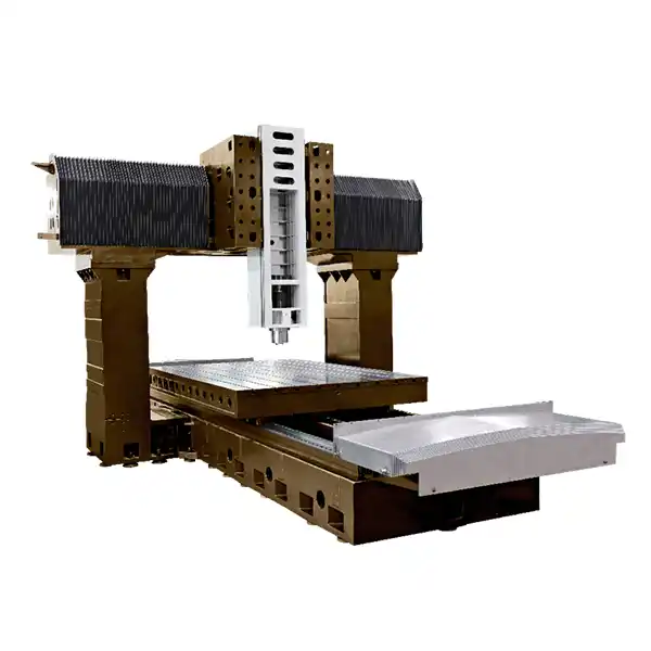
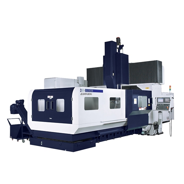
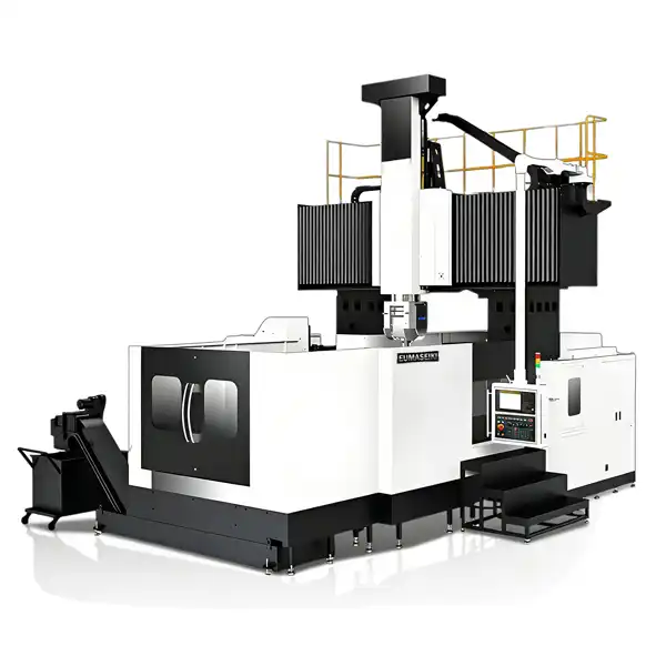
EUMASEIKI DM/DM5 series CNC gantry machining centers,The table adopts a double-layer reinforced rib hollow vibration suppression structure to enhance the stability of processing; Modular spindle design allows for the selection of gear type high torque spindles (full teeth) or embedded high-speed, high torque spindles to provide different cutting characteristics and meet diverse machining needs; Optional automatic exchange head library and vertical/horizontal tool changing system can be used to create a five face or 5-axis machining machine, with more flexible processing capabilities that fully meet your various processing needs today and in the future.
|
Specification |
Unit |
DM-2016i |
DM-2520i |
DM-3020i |
DM-4025i |
DM-6032i |
|
X-axis travel (worktable forward-backward) |
mm |
2000 |
2500 |
3000 |
4000 |
6000 |
|
Y-axis travel (spindle box left and right) |
mm |
1800 |
2000 |
2300 |
2500 |
3200 |
|
Z-axis travel (spindle box up and down) |
mm |
900 |
1000 |
1000 |
1000 |
1000 (1200) |
|
Distance from spindle nose to worktable surface |
mm |
180~1080 |
200~1200 |
200~1200 |
200~1200 |
200~1200 (200~1400) |
|
Distance between double columns of gantry |
mm |
1600 |
1900 |
2000 |
2800 |
3200 |
|
Worktable size |
mm |
1200×2200 |
1600×2500 |
1700×3000 |
2100×4000 |
6000×2800 |
|
Maximum worktable load |
kg |
6000 |
6000 |
7000 |
12000 |
18000 |
|
T-slot size (width × slot pitch × number) |
mm |
22×160×8 |
22×200×8 |
22×180×8 |
28×220×9 |
28×200 |
|
Spindle speed |
rpm |
6000 |
6000 |
6000 |
6000 |
6000 |
|
Spindle taper |
type |
ISO 50 |
ISO 50 |
ISO 50 |
ISO 50 |
ISO 50 |
|
Rapid feed rate (X/Y/Z) |
m/min |
20 / 20 / 12 |
15 / 15 / 15 |
12 / 12 / 10 |
12 / 12 / 12 |
10/ 10 / 10 |
|
Cutting feed rate (X/Y/Z) |
mm/min |
1~10000 |
1~8000 |
1~8000 |
1~8000 |
1~10000 |
|
Tool holder type |
type |
BT50 |
BT50 |
BT50 |
BT50 |
BT50 |
|
Tool magazine capacity |
pcs |
24 |
24 |
24 |
24/40 |
24/30/40 |
|
Maximum tool diameter |
mm |
125φ / 250φ |
125φ / 250φ |
φ110/φ200 |
125φ / 250φ |
125φ / 250φ |
|
Maximum tool length |
mm |
350 |
350 |
300 |
350 |
350 |
|
Maximum tool weight |
kg |
20 |
20 |
15 |
20 |
20 |
|
Tool changing method |
type |
Arm type |
Arm type |
Arm type |
Arm type |
Arm type |
|
Tool changing time (tool to tool) |
sec. |
5 |
5 |
5 |
5 |
5 |
|
Gear box |
type |
1:4.2 |
1:4.2 |
1:4.2 |
1:4.2 |
1:4 |
|
Main motor power |
Kw |
15/18.5 |
18.5~22 |
18.5/22 |
22/26 |
22/26 |
|
Main motor torque |
Nm |
143/236 |
118/140 |
147.2/175 |
140/165.5 |
140/165 |
|
Full-tooth ram torque |
Nm |
600.6/991.2 |
495/588 |
618/735 |
588/693 |
560/660 |
|
X/Y/Z-axis feed motor power |
kw |
3.0/ 3.0 / 3.0 |
3.0/ 3.0 / 3.0 |
3.0/ 3.0 / 3.0 |
6.0/ 7.0 / 7.0 |
6.0/ 7.0 / 7.0 |
|
X/Y/Z-axis feed motor torque |
Nm |
27/27/36 |
36/36/36 |
36/36/36 |
38/30/30 |
38~130/30~83/30~83 |
|
Cutting coolant motor power |
kw |
1.1+1.1 |
1.0+1.0 |
1.1+1.1 |
1.1+1.1 |
1.1+1.1 |
|
Air pressure requirement |
kg/cm2 |
6.5 |
6.5 |
6.5 |
6.5 |
6.5 |
|
Required power supply capacity |
kva |
40 |
45 |
45 |
60 |
50 |
|
XYZ positioning accuracy |
mm |
0.025/0.02 /0.01 |
0.018/0.018/0.018 |
±0.015/±0.012 /±0.008 |
±0.005/300 |
±0.01/300 |
|
XYZ repeat positioning accuracy |
mm |
0.016/0.0012/0.008 |
0.012/0.012/0.012 |
±0.008/±0.006/±0.005 |
±0.003/300 |
±0.01 |
|
Machine height |
mm |
4500 |
4800 |
4270 |
5400 |
5330 |
|
Machine size |
mm |
5800×4700 |
7000×3800 |
8400×4360 |
11200×5800 |
16000×5900 |
|
Machine weight |
kg |
22000 |
23000 |
35000 |
38000 |
65000 |
|
CNC system |
|
FANUC 0iMF |
FANUC 0iMF |
FANUC 0iMF |
FANUC 0iMF |
FANUC 0iMF |
Fully Enclosed Protective Cover
10.4-Inch Color Display
BT50 Spindle Structural Design
Unique Z-Axis Ram Structure with Full-Gear Gantry Design
Spindle Motor
X- and Y-Axis Linear Roller Guides;
Z-Axis High-Rigidity Hard guideway structure
Cutting Coolant System
Automatic Centralized Lubrication System
Spindle Air Blow Device
Chip Flushing Device
Electrical Cabinet Air Conditioning System
Manual Pulse Generator
RS232C Interface, USB Data Input/Output, Ethernet Port
Work Area Lighting
Pause and Complete Indicator Lights
Machine Anomaly Indicator
Auto Power-Off (M30)
Standard Tool Kit
Leveling Bolts and Foundation Blocks
Automatic Chip Conveyor and cart
FANUC 0iMF CNC system
Gear type spindle
Direct drive type spindle
Built-in spindle
Tool shank and pull bolt: DIN50/CAT50
Y-axis travel extension
Z-axis travel extension
Column height increase
Manual additional heads:35-degree head/90-degree head/universal head/extension head
Automatic additional heads 5 divisions:35-degree head/90-degree head/universal head/extension head
Tool magazine: 40/60/90/120 tools
X/Y/Z axis optical scales (HEIDENHAIN)
spindle temperature rise thermal compensation function
Oil circuit tool post interface
Spindle inner coolant (Form A)
Automatic tool length measurement device
Automatic workpiece measurement device
CNC rotary table
Disc-type oil-water separator
Mist cooling system