Aerospace components—from turbine blades to structural bulkheads—demand extreme accuracy, excellent surface finish, and the ability to machine complex freeform surfaces in challenging alloys like Inconel, titanium, or hardened stainless steel. One wrong machine choice can lead to repeated setups, tolerance stack‑ups, and costly rework.
This article walks you through the technical trade‑offs of different 5‑axis mill configurations and translates key performance indicators into real production benefits. By the end, you will have a clear decision framework to match a machine’s capabilities to your specific aerospace workpiece portfolio.
Before comparing configurations, it is worth understanding why five axes are often mandatory for airframe and engine components.
Reduced setups – A 5‑axis machine can reach five faces of a part in one clamping, eliminating alignment errors that creep in when you reposition the workpiece on a 3‑axis mill.
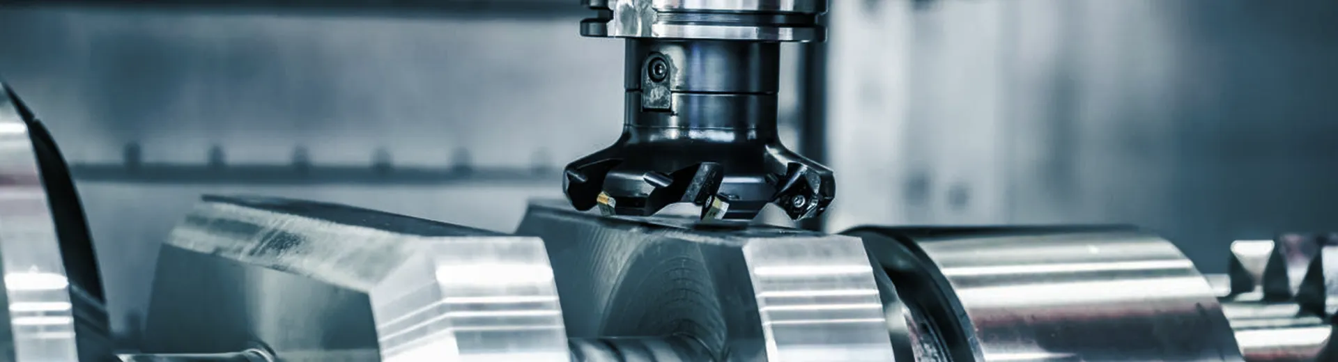
Shorter tools and better surface finish – By tilting the tool or table, you keep the cutting edge at an optimal angle, avoiding the “ball‑nose tip” problem. This yields faster cycle times and smoother aerodynamic surfaces.
Freedom from dedicated fixtures – Complex parts that once required custom angle plates or tombstone fixtures can be held directly, saving fixture design and production time.
Practical benefit for your shop floor: A single 5‑axis setup can turn a multi‑day process into a same‑day run, with fewer operators and lower scrap risk.
For applications where you machine thin‑walled housings or deep pockets, the ability to tilt the tool away from the workpiece also improves chip evacuation and reduces harmonic chatter.
To see how different machine series implement these capabilities, review the core 5‑axis machining center lineup from EUMASEIKI, which includes both table‑type and spindle‑out architectures.
Not all 5‑axis machines are built the same. The way the two additional rotary axes are arranged directly influences rigidity, work envelope, and part weight limits. The table below compares the most relevant types for aerospace machining.
| Configuration | How it moves | Typical aerospace part suitability | Key strength |
|---|---|---|---|
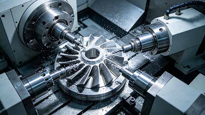
| Table‑type | A + B or A + C axes integrated into the worktable; spindle remains vertical. | Small to medium turbine blades, impellers, structural brackets | Excellent stiffness, good for heavy cuts; simpler 5‑axis simultaneous work. |
| Spindle‑out | Rotary axes built into the spindle head; table remains flat. | Large fuselage frames, wing spars, long parts | Unlimited work envelope; ideal for parts longer than machine X‑axis. |
| Gantry / moving crossrail | Bridge structure with head moving in X, Y, Z; table fixed. | Huge monolithic components | Highest rigidity for heavy‑duty cutting; supports very heavy parts. |
Table‑type is a popular starting point for aerospace job shops because it offers good 5‑axis simultaneous capability without sacrificing rigidity. However, the workpiece size and weight are limited by the rotary table’s load rating.
Spindle‑out keeps the workpiece stationary on a large fixed table. This is invaluable for long or odd‑shaped parts that exceed the machine’s travel. The trade‑off is that the moving head must be extremely stiff to avoid deflection during heavy milling.
Gantry designs are essentially oversized spindle‑out machines with a moving bridge. They are the go‑to choice for machining entire monolithic airframe structures, but they require more floor space and a higher investment.
If your part mix centers on small to medium nickel‑based superalloy components with tight blade geometries → table‑type is cost‑effective and precise.
If you routinely produce long stringers, spars, or large sheet‑metal assemblies → spindle‑out design gives you an unlimited X‑axis travel by simply adding rails.
If you process one‑piece bulkheads or landing gear components weighing several hundred kilograms → a gantry or moving‑column configuration offers unmatched stability.
Aerospace alloys are notorious for being “gummy” or abrasive. Here is a step‑by‑step checklist to evaluate any 5‑axis machining center for these materials.
1. Assess spindle power and torque at low RPM
Hard‑to‑cut materials require high torque at relatively low spindle speeds for roughing. A spindle that only delivers peak torque above 2,000 rpm will struggle with Inconel 718.
Why this matters to you: Insufficient low‑end torque forces you to take lighter cuts, doubling or tripling roughing time per part.
2. Check thermal stability of the rotary axes
Five‑axis work involves long continuous cutting paths. If the B‑axis or C‑axis drifts thermally after one hour of operation, your blade profiles will go out of tolerance. Look for direct‑drive torque motors with integrated cooling loops.
Why this matters: Prevents mid‑shift re‑calibration and scrap parts – especially critical for engine components with profile tolerances under ±15 microns.
3. Evaluate the control’s 5‑axis interpolation and tool center point (TCP) management
Even a mechanically perfect machine will produce gouges if the CNC cannot handle non‑linear rotary movements. Ensure the control supports TCP programming and dynamic collision checking.
Why this matters: Shortens programming time by 30–50% for complex aerospace geometries and eliminates crashes during dry‑run.
4. Measure work envelope relative to your largest part’s “envelope plus tool access”
Do not only look at X/Y/Z travels. For a spindle‑out machine, consider the swing radius of the swivel head. For a table‑type, verify that the tilted table does not hit the spindle housing when machining corners.
Why this matters: A seemingly large travel can become unusable if the head or table cannot reach certain features without over‑travel.
5. Review chip management and coolant pressure
Aerospace alloys generate stringy, abrasive chips. The machine must have a powerful chip conveyor and through‑spindle coolant.
Why this matters: Prevents chip recutting and reduces manual cleaning stops.
Scenario A – High‑volume production of turbine blades
Here, a table‑type 5‑axis with a tilting rotary table is often preferred. The parts are relatively small, and the need for simultaneous 5‑axis contouring on airfoil surfaces is constant. Key decision factors: high rotary axis acceleration and a spindle that can sustain 15,000+ rpm for finishing with small ball‑nose cutters.
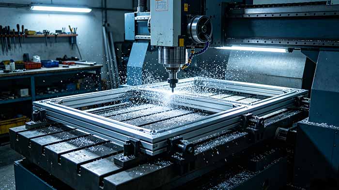
Scenario B – One‑piece fuselage frame made of aluminum 7050
A large, monolithic structural component measuring 2 meters in length. A spindle‑out machine on a fixed table allows the part to be clamped once while the head moves around it. Critical point: the A‑/B‑axis locking system must be rigid enough to handle heavy‑duty aluminum roughing.
Explore how swivel‑head and tilting‑table designs are applied to different aircraft component families on the aerospace application solutions page.
Now that you have mapped your workpiece size, material, and production volume to a preferred configuration, the remaining task is to compare how different machine families implement those architectures.
For table‑type 5‑axis simultaneous machining of smaller superalloy parts, you may examine models with compact footprints and high‑torque spindles. For spindle‑out designs that prioritise large envelope and heavy‑duty cutting, look for machines with dual‑drive rotary axes and reinforced ram structures.
To continue your technical research, read our detailed comparison of spindle‑out vs. table‑type 5‑axis machining for structural airframe parts.
How to Compare 3+2 vs. Simultaneous 5‑Axis Machining for Aerospace Prototypes
Understanding Mineral Casting Bed Benefits for High‑Precision Five‑Axis Milling
Five Ways to Reduce Cycle Time on Titanium Aerospace Components
Choosing Between a Rotary Table and a Trunnion Table for Blade Machining
This article is part of EUMASEIKI’s technical content library. No direct sales or pricing information is included. All technical discussions aim to help you make informed purchasing decisions.


