If you have ever watched a 5‑axis machining center in action, you have seen the spindle tilting, the table swinging, and the tool approaching a workpiece from angles that seem almost impossible. But how does the machine actually achieve those rotations? And why do different machines rotate in different ways?
Understanding the rotary motion of a 5‑axis machine is not just an academic exercise — it directly affects which parts you can machine, how accurately you can machine them, and how long each setup takes. This guide breaks down the mechanics of 5‑axis rotation, from the basic definitions of rotary axes to the three main configuration families that determine how your machine moves.
Before we explore how a machine rotates, we need to establish what we mean by “rotation.” A 5‑axis CNC machine combines three linear axes (X, Y, Z) with two rotary axes. The rotary axes are designated A, B, and C — and their definitions are surprisingly simple.
The rule is alphabetical: the A‑axis rotates around the X‑axis, the B‑axis rotates around the Y‑axis, and the C‑axis rotates around the Z‑axis. This holds true regardless of the machine brand or configuration.
| Rotary Axis | Rotates Around | Typical Movement |
|---|---|---|
| A‑axis | X‑axis | Tilts the table or head forward/backward |
| B‑axis | Y‑axis | Tilts the table or head side‑to‑side |
| C‑axis | Z‑axis | Rotates the table or head horizontally |
A 5‑axis machine uses two of these three rotary axes — typically A+C, B+C, or A+B combinations. The specific pair determines how the machine orients the tool relative to the workpiece.
Why this matters to you: The choice of rotary axis pair affects which geometries you can reach. An A‑C configuration excels at accessing undercuts and complex curved surfaces, while a B‑C configuration provides better access for large, flat workpieces.
Now that we know what the rotary axes are, the next question is: where do these rotations happen? The physical location of the rotary axes — in the table, in the spindle head, or split between both — defines the machine’s kinematics and determines its strengths and limitations.
There are three primary configuration families:
1. Table‑Table Configuration — Both Rotations in the Table
In a trunnion-style machine, both rotary axes are integrated into the worktable itself. The spindle remains stationary while the table tilts and rotates the workpiece into position.
How it rotates: The table swings on one axis while a built‑in rotary table spins on another. The A‑axis typically ranges from +30° to −120°, while the C‑axis offers full 360° rotation.
Best for: Smaller to medium parts, deep cavities, and undercuts. The stationary head also allows for heavier metal removal because the spindle can be geared for high torque at low RPMs.
Trade‑off: Part size and weight are limited by the table’s load capacity.
2. Head‑Head Configuration — Both Rotations in the Spindle
In a swivel‑head machine, both rotary axes are located in the spindle head. The table remains fixed.
How it rotates: The spindle head tilts and swivels, directing the cutting tool at virtually any angle while the workpiece stays stationary on the table.
Best for: Large or heavy workpieces that would be difficult to tilt or rotate. Since the table doesn’t move, the entire weight of the part transfers directly down through the machine base.
Trade‑off: Some of the work envelope must be used to accommodate the tool length as the head tilts — longer tools can significantly reduce the usable machining area.
3. Head‑Table Configuration — One Rotation in the Head, One in the Table
This configuration splits the two rotary axes: one resides in the spindle head, the other in the table.
How it rotates: For example, the table provides C‑axis rotation, while the head provides A‑ or B‑axis tilting.
Best for: Versatile applications requiring a balance between part size and machining flexibility. The table is typically large and robust, allowing multiple parts to be fixtured simultaneously.
Trade‑off: Increased system complexity and calibration effort compared to single‑location designs.
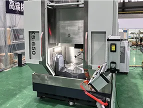
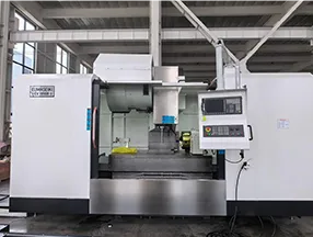
To see how these configuration principles are applied across different machine families, explore the 5‑axis machining center lineup from EUMASEIKI, which includes table‑type, swivel‑head, and hybrid architectures.
The way a machine rotates is not just a mechanical detail — it directly affects your machining outcomes. Here are five ways rotary motion translates into real‑world results:
With two rotary axes, a 5‑axis machine can access up to five faces of a part in a single clamping. Each setup eliminated means one less opportunity for alignment error and one less fixture to design and build.
By tilting the tool or table, the cutting edge can maintain an optimal angle relative to the surface throughout the cut. This eliminates the “ball‑nose tip” problem common in 3‑axis machining, producing smoother aerodynamic surfaces and reducing or eliminating secondary finishing.
In a swivel‑head or hybrid machine, the ability to tilt the head often allows the use of shorter cutting tools. Shorter tools are more rigid, which means less deflection, better surface finish, and longer tool life.
Trunnion‑style machines can tilt the table farther than most swivel‑head designs can tilt the spindle — sometimes up to 110° in one direction. This provides exceptional access to the underside of parts, making these machines ideal for components with deep undercuts.
Continuous 5‑axis machining generates heat in the rotary axes. If the B‑axis or C‑axis drifts thermally after an hour of operation, your part tolerances will suffer. This is why high‑precision machines use direct‑drive torque motors with integrated cooling — a detail that becomes critical when machining aerospace or medical components with tolerances under ±15 microns.
It is worth noting that not all 5‑axis machines use their rotary axes the same way. There are two distinct modes of operation:
3+2 machining: The rotary axes position the workpiece or tool at a fixed angle, then lock in place while the three linear axes do the cutting. This is like having a 3‑axis machine that can approach from any angle, but without continuous motion during the cut.
Simultaneous 5‑axis machining: All five axes move continuously during the cut, allowing the tool to follow complex curved paths in a single pass.
When to choose which: 3+2 is often sufficient for parts with flat faces at multiple angles. Simultaneous 5‑axis is essential for parts with freeform surfaces where the tool must constantly change orientation to maintain optimal cutting conditions.
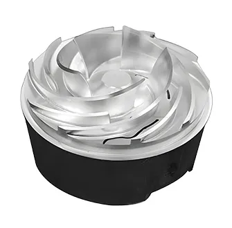
A turbine blade requires continuous 5‑axis contouring to machine the airfoil surface. A table‑table configuration with A‑ and C‑axes is often preferred here. The part is relatively small, and the table’s ability to tilt and rotate provides excellent access to the curved surfaces. Key consideration: the rotary axes must have high acceleration to minimize cycle time on complex toolpaths.
A large die or mold may weigh several hundred kilograms. A swivel‑head configuration allows the workpiece to remain stationary on a fixed table while the spindle head does all the rotating. This avoids the need to tilt a heavy table, preserving accuracy and simplifying workholding. Key consideration: the head must be extremely rigid to handle heavy cutting loads without deflection.
For a part that is several meters long, a head‑table hybrid or gantry configuration provides the best solution. The table can be extended as needed, and the head provides the tilting motion while the part remains stationary.
Explore how different 5‑axis configurations are applied to specific industries on the aerospace and automotive solutions page.
Now that you understand how a 5‑axis machine rotates — and why the location of those rotary axes matters — you are better equipped to evaluate which configuration suits your part portfolio. The key questions to ask are:
How large and heavy are your typical parts?
Do you need continuous 5‑axis contouring or positional 3+2 machining?
What materials are you cutting?
Once you have clarified these decision factors, comparing the specific specifications of available machine families becomes the next logical step. You can review the 5‑axis machining center lineup for table‑type configurations suited to compact precision parts, or explore swivel‑head and hybrid designs for larger workpieces.
Continue your technical research with our detailed comparison of trunnion‑table vs. swivel‑head 5‑axis machining for structural components.
Trunnion‑Table vs. Swivel‑Head 5‑Axis Machining — Which Configuration Fits Your Shop?
Aerospace Parts? Use This 5‑Axis Mill | Key Configurations | EUMASEIKI
Five Ways to Reduce Cycle Time on Complex 5‑Axis Parts
3+2 vs. Simultaneous 5‑Axis Machining — A Practical Decision Guide
How Mineral Casting Beds Improve Stability in 5‑Axis Machining Centers
This article is part of EUMASEIKI’s technical content library. No direct sales or pricing information is included. All technical discussions aim to help you make informed purchasing decisions.


